FAFO: Overclocking Bitaxe or Nerd*axe miners and the risks to the Voltage Regulators Chain (VRM)
- May 10
- 8 min read
Updated: May 12
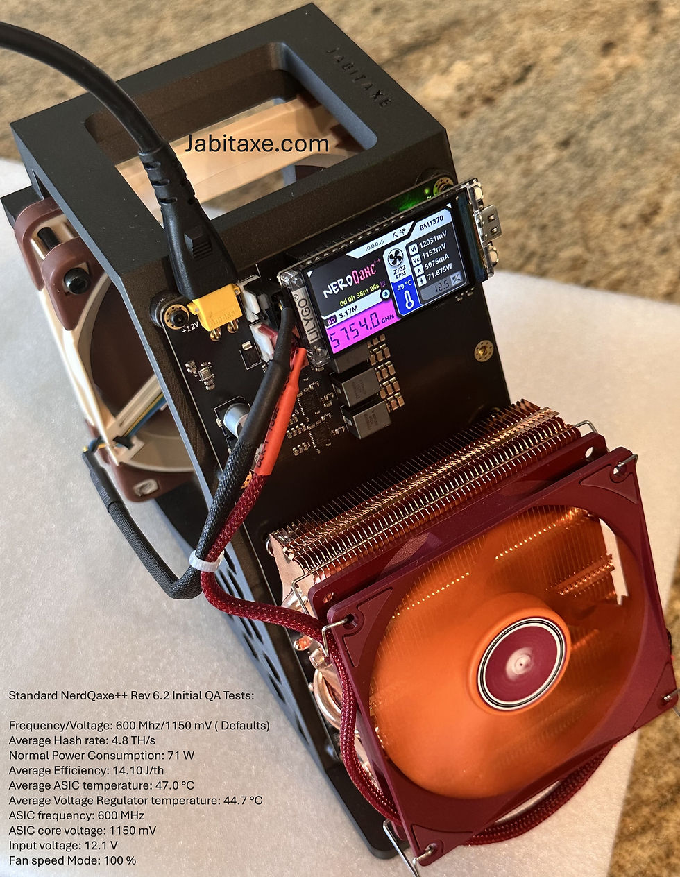
By Developeralgo222 (Jabitaxe.com )

The Bitaxe and NerdQaxe miner series use CSD95472Q5MC from Texas Instruments as the Voltage regulators.
The CSD95472Q5MC NexFET™ power stage from Texas Instruments has an operating junction temperature (TJ) range of -55 to 150 C
Key thermal and design specifications for this 5mm x 6mm VSON-CLIP (DMC) SMD package include:
Operating Junction Temperature (TJ): -50 to 150C
Storage Temperature (Tstg): -50 to 150C
Thermal Resistance (Junction to Pad/Case): While the datasheet provides comprehensive junction-to-board (RθJB) information, the DualCool™ package allows for significant heat extraction via the top and bottom, effectively designed for high-density, high-current operation (60A continuous, Max: 90A).
Thermal Protection: The device includes built-in overtemperature protection to prevent damage, with the TAO/FAULT pin providing an analog voltage proportional to the die temperature (600 mV at 0 ℃)
For optimal performance, the device should be soldered to a thermal pad with adequate, heavy-copper, multi-layer PCB design for efficient heat transfer to the board.
Calculate Operating Junction temperature (TJ):
To calculate the operating junction temperature (TJ) for the CSD95472Q5MC NexFET™ power stage from the junction to the PCB pad (bottom), use the thermal resistance from the junction to the board (RθJB).
The formula is:
TJ = TPCB + PLoss + R𝜽JB
1. Identify Necessary Parameters
TPCB (Board Temperature): The temperature of the PCB measured within 1 mm of the package.
PLoss (Power Dissipation): Total power loss in watts (W).
R𝜽JB (Thermal Resistance Junction-to-Board): According to the datasheet, this value is based on a 1-inch2 (6.45 cm2), 2-oz (0.071 mm thick) Cu pad on a 1.5 inches x 1.5 inches, 0.06-inch (1.52-mm) thick FR4 board.
Note: For the CSD95472Q5MC, typical operating losses are low, e.g., ~2.3 W at 30 A (VIN=12V, VDD=5V, VOUT=1.2V).
2. Calculation Example
Assuming a design with:
Board Temperature (TPCB ) = 80 ℃
Power Loss (PLoss ) = 2.0 W
R𝜽JB (Estimated based on similar 5x6 mm NexFETs) = ~ 2 - 3 ℃/W (Note: Precise R𝜽JB value should be taken from the specific revision of the datasheet)
TJ = 80℃ + ( 2.0 W x 2.5 ℃/W)
TJ = 80℃ + 5℃
TJ = 85℃
Summary Checklist
Measure TPCB using a thermocouple at the hottest point on the PCB near the device.
Calculate PLoss based on your operating conditions (VIN, VOUT, IOUT, switching frequency).
Use R𝜽JB to find the delta from the PCB.
The device must operate within the junction temperature range of -55°C to 150°C (TJ)
Why Overclocking Bitaxe or NerdQaxe miners at high CSD95472Q5MC Operating Junction temperatures will most likely cause a short
When the operating junction temperature (TJ) of CSD95472Q5MC smart power stage significantly exceeds its maximum rated limit (+150°C), it triggers physical, electrical, and mechanical degradation mechanisms that permanently short-circuit the device internally.
Because the junction-to-pad path represents the primary thermal highway designed to dump heat into the PCB, a breakdown in this thermal interface forces the internal die temperature to spike aggressively, resulting in a short-circuit through the following concurrent failure modes:
1. Thermal Runaway via Intrinsic Carrier Activation
At standard operating temperatures, a MOSFET's current is carried by intentionally doped majority carriers.
The Physics: As the temperature spikes past critical structural thresholds, the silicon undergoes intrinsic semiconductor conduction. Thermal energy forces valence electrons to jump to the conduction band natively.
The Failure: The gate loses control over the channel. The leakage current across the internal parasitic structures increases exponentially with temperature. This uncontrolled leakage generates localized heat, further increasing the temperature until the silicon melts, leaving behind a permanent, highly conductive carbonized short-circuit path.
2. Parasitic BJT Latch-Up
The integrated NexFET power stage contains parasitic Bipolar Junction Transistors (BJTs) inherent to all vertical MOSFET geometries.
The Physics: Under extreme temperatures, the internal body-source shunt resistance increases while the forward-bias turn-on threshold voltage (VBE) of the parasitic BJT decreases.
The Failure: High (TJ) causes the parasitic BJT to turn on. Once latched, this structure behaves like a thyristor and cannot be turned off by the PWM or driver logic. The resulting uncontrolled current surge immediately destroys the gate-oxide structure or melts the source metallization, shorting the input voltage (VIN) directly to ground (PGND) or the switch node (VSW ).
3. Interlayer Dielectric (ILD) Fracture & CTE Mismatch
The CSD95472Q5MC utilizes a complex, multi-die system-on-package design with an advanced DualCool™ package clip.
The Physics: Silicon, the copper clip, the plastic molding compound, and the underlying PCB pad all possess radically different Coefficients of Thermal Expansion (CTE).
The Failure: Severe temperature gradients along the junction-to-pad path create intense thermo-mechanical shear stress. This stress fractures the internal sub-micron interlayer dielectrics or degrades the underlying die-attach solder layers. Once the dielectric barrier cracks, the high-voltage high-side drain metallization physically bridges with low-voltage gate lines or the low-side source, creating a hard electrical short.
4. Gate Oxide Breakdown
Extreme heat heavily degrades the dielectric strength of the silicon dioxide (SiO2) insulating layer between the gate and the channel.
The Physics: High temperatures accelerate a phenomenon known as Time-Dependent Dielectric Breakdown (TDDB).
The Failure: High thermal energy enables electrons to tunnel through the thin oxide insulator layer easily. Once a localized micro-tunneling path forms, current rushes through it, creating a thermal hot spot that blows out the gate oxide and permanently welds the Gate to the Source or Drain.

Scenario 1:
What if we use Power input Vin = 12V , CSD95473Q5MC Switching Frequency = 500 KHz, BM1370 Asic Voltage = 1.2V, Total Asic Current Out = 100A and PCB Copper thickness = 2 oz, in a 3-phase CSD95472Q5MC design as in Nerd*axe Variant miners
With a 3-phase configuration utilizing the CSD95472Q5MC, your 100A total load splits down to a nominal 33.33A per phase. This setup sits directly in the optimal efficiency sweet spot for this smart power stage, mitigating the severe thermal risks of the single-phase design.
Operating at 12V, 500 kHz, and 2-oz copper, the thermal and electrical dynamics break down as follows:
1. Per-Phase Power Dissipation Snapshot
Balanced Thermal Load: At 33.33A per phase, the CSD95472Q5MC experiences manageable I2R conduction losses combined with moderate 500 kHz switching losses.
Calculated Loss Profile: Based on TI NexFET performance curves, each phase will dissipate roughly 2.8W to 3.5W of total power (depending slightly on your output voltage/duty cycle). Across all three phases, total power stage dissipation settles around 9W to 10.5W.
2. Junction-to-Pad Thermal Behavior on 2-oz Copper
Junction Temperature (TJ) Estimate: The junction-to-case (pad) thermal resistance ( R𝜽JC(pad) ) of this package is very low, at roughly 1.4°C/W. Dissipating ~3.5W means the temperature delta between the internal silicon junction and the underlying PCB pad is only about 5°C.
PCB Performance: The 2-oz copper acts as an excellent lateral heat spreader. If paired with a standard matrix of thermal vias to internal ground planes, the case-to-ambient thermal resistance ( R𝜽CA ) will stay around 12°C/W to 15°C/W. Your estimated peak operating junction temperature will hover safely around 70°C to 80°C (at a 25°C ambient), providing an massive 70°C safety margin below the +150°C destruction limit.
3. Key Layout and Electrical Requirements to Avoid Shorts
While the 3-phase design prevents instant thermal melting, you must prevent localized electrical stress at 500 kHz from creating an internal short:
Strict Phase Interleaving: The 3 phases must be interleaved at a 120° phase shift by your PWM controller. This keeps the input ripple current low and prevents all three phases from pulsing simultaneously, which would cause severe localized voltage sagging and high-frequency inductive ringing.
Input Decoupling Matrix: Place at least two high-quality ceramic capacitors (e.g., 10µF, 25V, X7R in a 0805 or 1206 footprint) immediately adjacent to the VIN and PGND pins of each individual power stage. At 500 kHz, parasitic loop inductance will cause high-voltage transients on the switch node (VSW ).If these transients overshoot the 12V line and hit the device's absolute voltage limits, the gate oxide will puncture, causing a catastrophic short.
Thermal Via Density: Directly underneath the primary thermal pad of each phase, you must implement a 3x3 or 4x4 matrix of filled, via-in-pad structures (typically 0.2mm to 0.3mm drill size). Without these vertical thermal pathways, heat will pool under the 2-oz copper surface layer, raising the local case temperature and eroding your safety margin.
Scenario 2:
What if we use Power input Vin = 12V , CSD95473Q5MC Switching Frequency = 400 KHz, BM1370 Asic Voltage = 1.2V, Total Asic Current Out = 100A and PCB Copper thickness = 2 oz, in a 3-phase CSD95472Q5MC design as in NerdQaxe Variant miners
Dropping the switching frequency to 400 kHz in this 3-phase, 100A configuration optimizes the system. It reduces thermal stress and provides an even wider safety margin against short-circuit failures.
At 12V, 400 kHz, and 2-oz copper, the performance shifts as follows:
1. Reduced Power Dissipation Profile
Switching Loss Drop: Lowering the frequency from 500 kHz to 400 kHz reduces dynamic switching losses by roughly 20%.
Conduction Stability: Conduction losses remain stable at 33.33A per phase ( 100A / 3-phases).
Total Per-Phase Loss: Total dissipation drops to an estimated 2.4W to 3.0W per phase (down from 3.5W). Total power stage heat drops to under 9W across the board.
2. Enhanced Junction Temperature Safety Margin
Silicon Temperature (TJ) : The lower 3.0W heat load reduces the internal thermal gradient.
Operating Estimate: The junction temperature settles around 65°C to 75°C in standard ambient environments.
Short-Circuit Protection: This leaves a massive 75°C to 85°C safety buffer before reaching the +150°C silicon breakdown threshold.
3. Output Filter and Inductor Trade-offs
Shifting to 400 kHz changes the requirements for the surrounding passive components:
Higher Inductance Needed: Lower frequencies increase peak-to-peak inductor ripple current. You must increase your phase inductance value (typically to 150nH or 220nH) to keep ripple under control.
DCR Awareness: Ensure the larger inductors feature ultra-low DC Resistance (DCR). High inductor DCR will generate external heat that can bleed through the 2-oz copper layer into the CSD95472Q5MC thermal pad.
4. Layout Verification Checklist
To guarantee this 400 kHz 3-phase system does not fail:
Interleaving: Program your PWM controller for a strict 120° phase separation to minimize input capacitor ripple stress.
Input Capacitors: Place a combination of 0603 high-frequency and 1206 bulk ceramic capacitors directly across the VIN and PGND pins of each phase.
Via Architecture: Maintain a solid matrix of solid-filled or copper-plated thermal vias directly inside the 2-oz pad to transition heat to internal ground layers.
Scenario 3:
What if we use Power input Vin = 12V , CSD95473Q5MC Switching Frequency = 400 KHz, BM1370 Asic Voltage = 1.2V, Total Asic Current Out = 100A and PCB Copper thickness = 2 oz, in a 6-phase CSD95472Q5MC design with TPS53667 Controller compared to 3-Phase as in NerdQaxe Variant miners and 4-Phase designs
Using a 6-phase configuration with the TPS53667 is the most efficient and thermally stable approach for a 100A load. It effectively "overbuilds" the power delivery, ensuring the BM1370 receives incredibly clean power with minimal heat waste.
Side-by-Side Comparison
Metric | 3-Phase | 4-Phase | 6-Phase (TPS53667) |
Current per Phase | 33.3A | 25.0A | 16.7A |
Component Stress | Moderate (55% load) | Low (41% load) | Very Low (27% load) |
Loss per Phase | ~3.0W | ~2.2W | ~1.4W |
Total Heat (approx.) | 9.0W | 8.8W | 8.4W |
Effective Ripple Freq | 1.2 MHz | 1.6 MHz | 2.4 MHz |
Stability/Overclock | Good | Better | Best |
Key Advantages of the 6-Phase Design
Thermal Distribution: While the total wattage lost as heat is only slightly lower than the 4-phase, it is spread across 50% more surface area. Combined with 2 oz copper, this eliminates hot spots entirely. The MOSFETs will run significantly cooler, which is vital if the miner is in a small enclosure.
Voltage Ripple & Stability: The TPS53667 interleaves 6 phases, meaning the output ripple is naturally cancelled out. At 2.4 MHz effective frequency, the BM1370 sees a near-perfect DC voltage. This allows you to lower the ASIC voltage ( Vcore ) closer to the "edge" for better efficiency without the chip crashing due to noise.
Efficiency Peak: The CSD95472Q5MC hits its peak efficiency between 15A and 20A. A 6-phase design keeps you exactly in this "sweet spot," whereas a 3-phase design pushes the chips into a slightly less efficient, hotter part of their curve.
Inductor Optimization: In a 6-phase setup, the individual inductors only need to handle ~17A. This allows you to use physically smaller inductors with lower DCR (Direct Current Resistance), further reducing losses compared to the beefy inductors required for 3-phase.
Summary
The 3-phase design is "sufficient," the 4-phase is "optimal," but the 6-phase TPS53667 design is "industrial grade." It provides the highest hashrate potential for the BM1370 by providing the most stable power delivery possible in this form factor.


Comments